Unity Products:Amplify Shader Editor/Add and Unity Products:Amplify Shader Editor/Append: Difference between pages
AmplifyWiki (talk | contribs) m (1 revision imported) |
ampwiki>Kebrus mNo edit summary |
||
| Line 1: | Line 1: | ||
[[Unity_Products:Amplify_Shader_Editor/Nodes | Back to Node List]] | [[Unity_Products:Amplify_Shader_Editor/Nodes | Back to Node List]] | ||
== Append Node == | |||
''' | The Append node ''( shortcut: V key )'' outputs a vector which results of the combination of channels from different input sources. | ||
<br/> | |||
Input ports amount is both dependent on the chosen [[#paramOutputType|Output Type]] and incoming data type. | |||
P.e. if ''Output Type'' is set to ''Vector3'' then by default it will show three input ports ''X'',''Y'',''Z''. When connecting a ''Vector2'' data type to input port ''X'', it will automatically change its name to ''XY'', the next port will also be renamed to ''Z'' and hide the third unnecessary port. | |||
<img class="responsive-img" src="http://wiki.amplify.pt/images/NodeDetail/ | '''NOTE:''' Automatic port usage only is done if next channels are unoccupied. P.e. if connecting a Vector3 type data into an Append node's X input port which has an already created connection on its Z input port will only occupy X and Y channels. | ||
<img class="responsive-img" src="http://wiki.amplify.pt/images/NodeDetail/AppendNode.jpg"> | |||
<br/><font size="1">Nodes used: | <br/><font size="1">Nodes used: | ||
[[Unity_Products:Amplify_Shader_Editor/Texture_Sample|Texture Sample]], | [[Unity_Products:Amplify_Shader_Editor/Texture_Object|Texture Object]], | ||
[[Unity_Products:Amplify_Shader_Editor/ | [[Unity_Products:Amplify_Shader_Editor/Vertex_Position|Vertex Position]], | ||
[[Unity_Products:Amplify_Shader_Editor/Append|Append]], | |||
[[Unity_Products:Amplify_Shader_Editor/Texture_Sample|Texture Sample]], | |||
[[Unity_Products:Amplify_Shader_Editor/Vertex_Normal|Vertex Normal]], | |||
[[Unity_Products:Amplify_Shader_Editor/Lerp|Lerp]] | |||
</font> | </font> | ||
| Line 16: | Line 23: | ||
|- | |- | ||
! style="width: 10%;" | Node Parameter !! Description !! style="width: 10%;" | Default Value | ! style="width: 10%;" | Node Parameter !! Description !! style="width: 10%;" | Default Value | ||
|- | |- | ||
| id=" | | id="paramOutputType" | Output Type | ||
| | | Defines resulting vector data type. This option has a direct impact on the amount of available inputs to inject new data. | ||
The available output types are: | |||
* '''Vector2:''' 2-channel data type | |||
* '''Vector3:''' 3-channel data type | |||
* '''Vector4:''' 4-channel data type | |||
* '''Color:''' 4-channel data type | |||
| 0 | | 0 | ||
|} | |} | ||
{| class="wikitable" style="width: 100%;" | {| class="wikitable" style="width: 100%;" | ||
| Line 31: | Line 38: | ||
! style="width: 10%;" | Input Port !! Description !! style="width: 10%;" | Type | ! style="width: 10%;" | Input Port !! Description !! style="width: 10%;" | Type | ||
|- | |- | ||
<!--| [ X | Y | Z | W ] --> | |||
| X, Y, Z or W | |||
|Data to be appended into new ''Vector'' output. | |||
Amount and name of input ports is both dependent on current ''Output Type'' and incoming data type. | |||
| Vector4<sup id="ref1">[[#anchor|[1]]]</sup> | |||
| | |||
| | |||
| | |||
| | |||
|} | |} | ||
---- | ---- | ||
# <span id="anchor1">'''[[#ref1|^]]'''</span> Port automatically adapts to all connection types except Matrices and [[Unity Products:Amplify Shader Editor/Texture Object|Sampler]] types. | |||
| | |||
| | |||
[[Unity_Products:Amplify_Shader_Editor/Nodes | Back to Node List]] | [[Unity_Products:Amplify_Shader_Editor/Nodes | Back to Node List]] | ||
[[Category:Nodes]][[Category: | [[Category:Nodes]][[Category:Vector Operators]] | ||
Revision as of 11:29, 16 February 2018
Append Node
The Append node ( shortcut: V key ) outputs a vector which results of the combination of channels from different input sources.
Input ports amount is both dependent on the chosen Output Type and incoming data type.
P.e. if Output Type is set to Vector3 then by default it will show three input ports X,Y,Z. When connecting a Vector2 data type to input port X, it will automatically change its name to XY, the next port will also be renamed to Z and hide the third unnecessary port.
NOTE: Automatic port usage only is done if next channels are unoccupied. P.e. if connecting a Vector3 type data into an Append node's X input port which has an already created connection on its Z input port will only occupy X and Y channels.
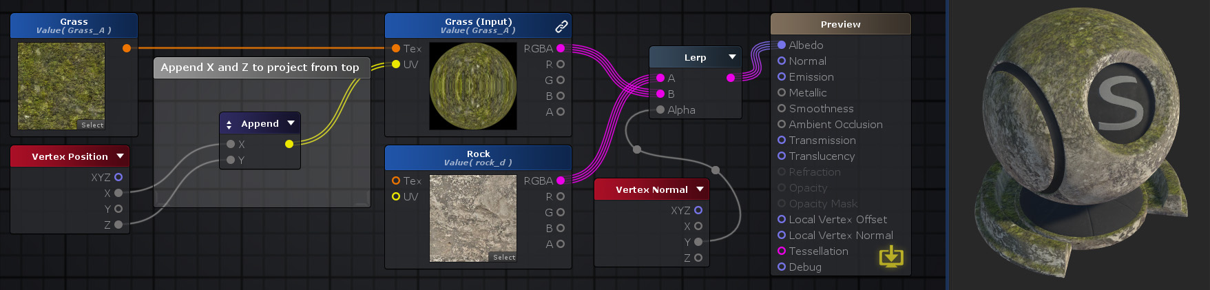
Nodes used:
Texture Object,
Vertex Position,
Append,
Texture Sample,
Vertex Normal,
Lerp
| Node Parameter | Description | Default Value |
|---|---|---|
| Output Type | Defines resulting vector data type. This option has a direct impact on the amount of available inputs to inject new data.
The available output types are:
|
0 |
| Input Port | Description | Type |
|---|---|---|
| X, Y, Z or W | Data to be appended into new Vector output.
Amount and name of input ports is both dependent on current Output Type and incoming data type. |
Vector4[1] |