Unity Products:Amplify Shader Editor/Manual
Product Page - Included Shaders - Manual - Shader Functions - Tutorials - API - Shader Templates - Scriptable Rendering Pipeline - Nodes - Community Nodes
Installation1. Open AmplifyshaderEditor###.unitypackage 2. After Unity loads it will display the “Importing package” window, select All and click Import 3. Amplify Shader Editor should now be installed in your Unity project and it should have the following directory structure:
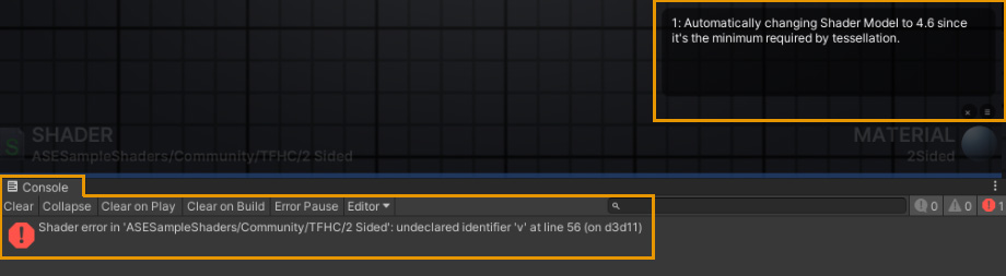
Help! My Shaders are all Pink!Don't panic. A shader being pink(magenta) is Unity's way of letting you know that something is not working or properly configured. 1. You're using the wrong Shader Type for your current Renderer.
2. You have a shader error that's causing it from executing as expected.
The Editor
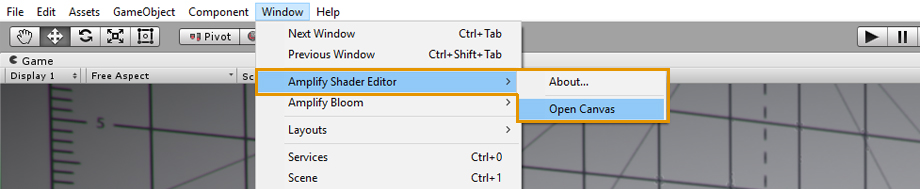
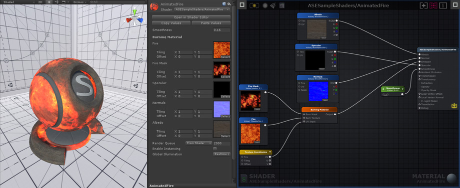
Open the Amplify Shader Editor canvas, dock it, use it in a separate window, or even another monitor. The editor opens automatically when you double-click an ASE material or shader.
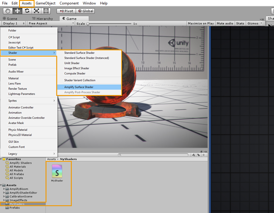
ASE shaders can be created directly in the Project tab or via the Menu under Assets > Create > Shader > Amplify Surface Shader.
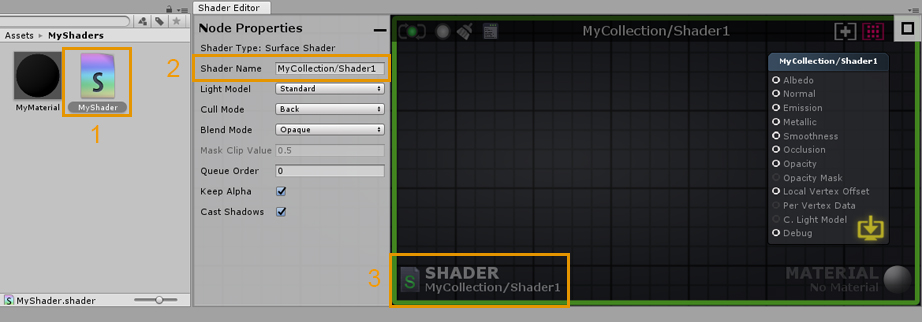
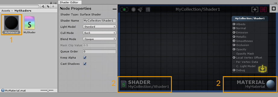
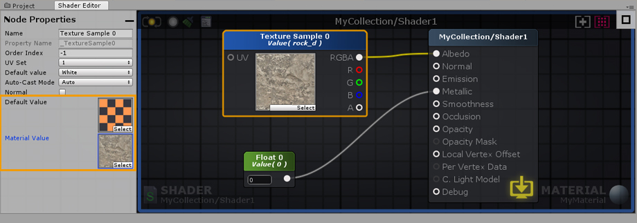
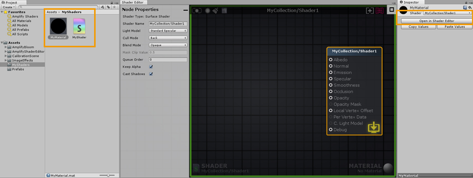
1. Double-click an ASE shader to open it in the ASE canvas. Alternatively, you can open the shader directly in its inspector tab by clicking on the Open in Shader Editor button. 2. Name your shader directly in the Node Properties tab, you can add your own category by using a forward slash (/) separator. Keep in mind that shader file names are unique and have to be set manually in the Project Explorer tab. You can use different names for the file and actual shader. 3. This area shows the current shader, clicking it will locate and select the shader in the Project Explorer tab. Notice the green outline, it’s a visual aid that lets you know that only the shader is currently open.
1. Double-click a material that uses an ASE shader to open both the shader and the material in the ASE canvas. Alternatively, you can open it directly in the material inspector tab by clicking on the Open in Shader Editor button. 2. By opening the material, both the active shader and material are shown in the lower canvas area. As with the shader, clicking on it will locate and select the material in the Project Explorer tab. Notice the blue outline, it’s a visual aid that lets your know that both the shader and material are currently open. Canvas UI Interaction
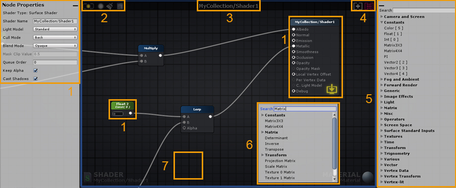
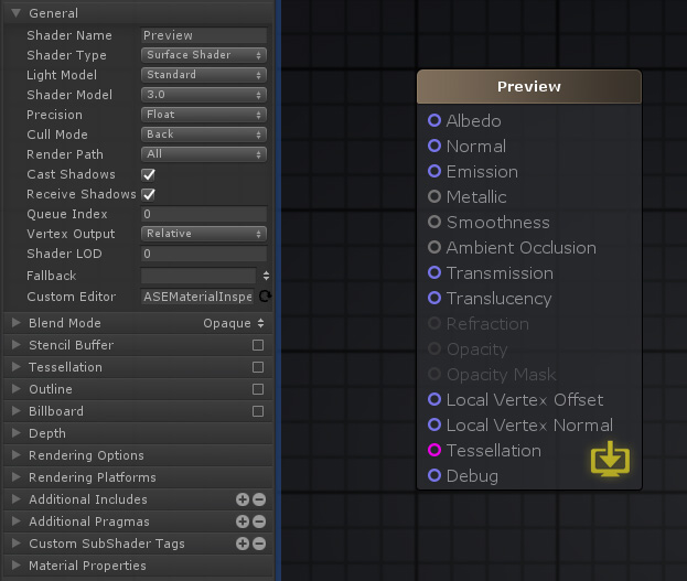
1. Node properties can be adjusted in the left tab. Select a node, or the Output Node, to reveal its parameters. Some values can be adjusted directly in the actual node. Output Node properties are always shown on this tab if no node or multiple nodes are selected. The Output Node Properties tab can be minimized by clicking the minus button in the upper right corner of the tab. 2. Minimalist Save/Update/Clear/Edit buttons. Gray when unavailable or disabled, green when up-to-date, yellow when outdated.
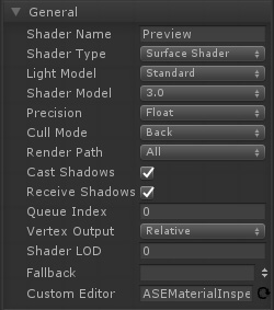
3. Shader category and name. 4. Canvas view adjustment.
5. The Node Palette tab is a searchable node list where you can select and drag out nodes directly onto the canvas area. The Node Palette tab can be minimized by clicking the minus button in the upper left corner of the tab. 6. Right-click anywhere on the canvas to bring up a searchable node list, click on the node name to create it. Sharing ContentAs of version v1.6.8.002, you can now take full canvas screenshots of your shaders using the Camera button. Additionally, you can also share nodes by copying and pasting a link directly into your canvas using the link sharing button.
7. Hold a shortcut key and click anywhere on the canvas to create a new node. Shortcut keys are shown inside [ ] placed in front of their respective node names on the Palette Tab. For example: Key ‘1’ for a Float and Key ‘5’ for a Color node.
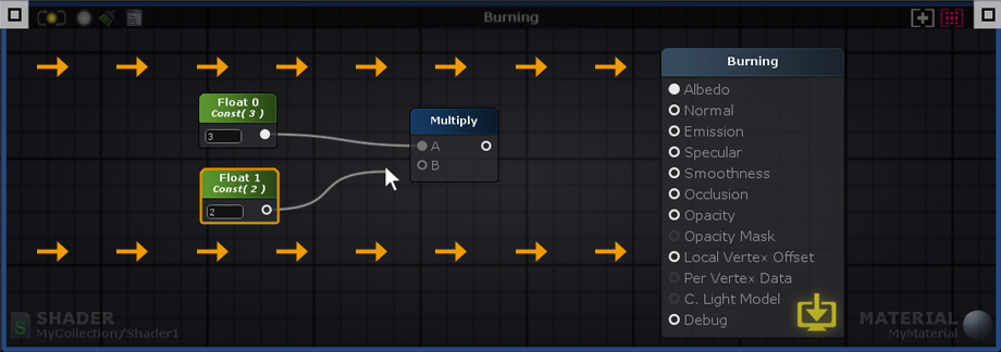
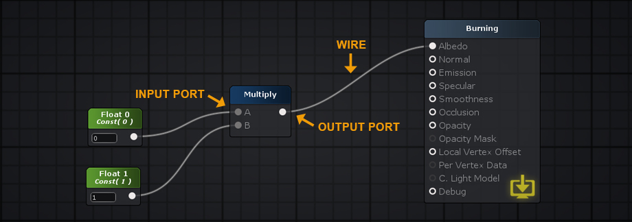
Data flows from left to right – Input Port > Processed Data > Output Port. Only nodes directly or indirectly connected to a Output Node are analyzed and used to generate the final shader instructions. If a node contains unconnected Input Ports, ASE will use internal data during the processing phase. Internal data values can be edited via the Node Property tab.
Nodes Nodes can be selected by either left mouse clicking on them or left mouse drag a box selection over them. Nodes can be appended or removed from a selection by holding the ‘Shift’ key and clicking on it. Press ‘CTRL/CMD+A’ to select everything. Deselect everything by left mouse clicking over an empty space on the node canvas. Move selected nodes by holding your left mouse button over them and dragging. Wires Delete a wire by holding the ‘Alt’ key and clicking on a node port or drag a connection to an empty canvas space and left click. Wires connected to selected nodes are highlighted to denote data flow, from the leftmost node to the rightmost node. Connections Create connection by left clicking and dragging a wire either from an output port into an input or from an empty input port to an output port. Left mouse holding on a already connected input port removes wire ending from it and locks it to the mouse cursor so you can drag it to another port. Drag a wire onto an empty canvas space and the context menu automatically appears and if a node type is selected a connection is made with the first valid port. Ports Output ports can be connected to multiple input ports but input ports accept a single input. Wires automatically snap to ports near the mouse cursor. For easier use, the active port area is quite forgiving, you can even drop your wires directly onto the port name. View Right mouse or middle mouse button drag to pan the view. The canvas will scroll automatically when box selecting or moving selected nodes away from the visible workspace area. You can Zoom In/Out via the mouse scroll wheel. The amount of zoom out is dynamically determined from the nodes positioning on the canvas. Tabs Both the Node Properties and Node Palette windows are automatically minimized when reducing the ASE window width below a value of 750px. You can always maximize them by clicking the rectangular button. Material and Shader Mode
You can work with ASE in one of two modes, shader or material, depending if you load the shader file from a shader or a material asset. The canvas border serves as a visual indicator of the active mode, a green outline is shown for the shader mode and a blue outline for the material mode.
Values set in a shader are commonly referred to as Default Values. Any changes made to the Default Values of any given shader will automatically affect all materials using it. When simultaneously editing a material and shader, pay close attention to which values are being altered.
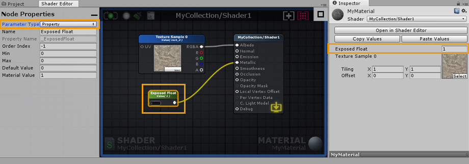
Unlike the Default Values in a shader, material values can be unique. material values are only shown when working in the material mode ( with both material and shader opened ). Only nodes which represent variables ( Color, Float, Int, Vector, Matrix ) have a Parameter Type dropdown and can be set to Property. Default values are always copied to material values when selecting Property or Uniform parameter type. Each material can be adjusted in order to create an unlimited number of variations, while still using the same shader. You can think of your materials as instances of your shader, each instance is unique but created using the same set of Default Values.
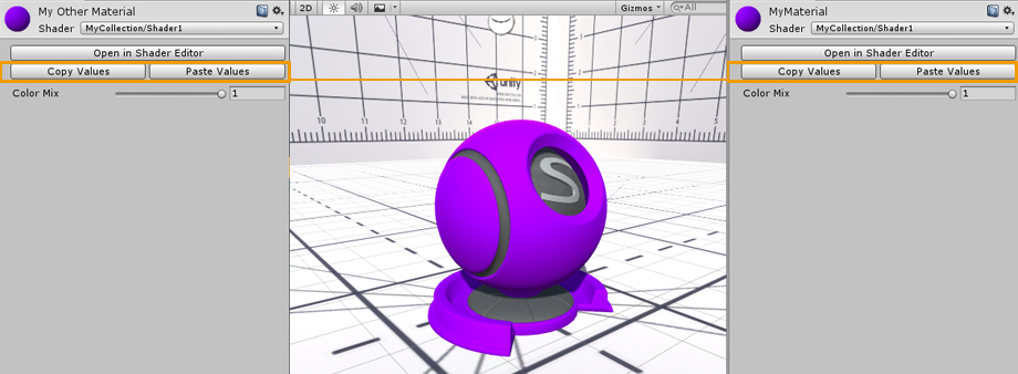
You can Copy and Paste property values between materials using the same ASE shader. The Open in Shader Editor button provides a quick way to open both the material and shader used in the Amplify Shader Editor.
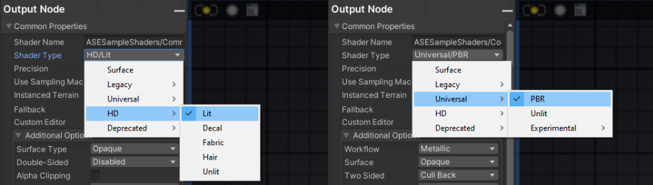
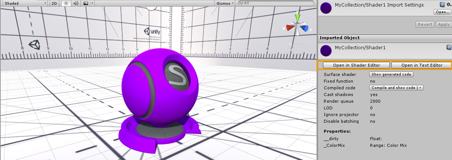
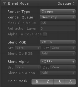
Shaders can also be opened directly via their inspector tab by clicking on the Open in Shader Editor button. Alternatively, click on Open in Text Editor to open it in your current code editor. Output Node (Built-in Renderer)ATTENTION This section serves solely as an example of common parameters found in the Standard Built-in Renderer PBR Shader. Depending on the shader type used, you might have a different set of parameters available used or an entirely different order. If you're looking for specific HDRP or URP information, be sure to check the relevant page: Scriptable Rendering Pipeline Portions of this section have been acquired directly from the Unity Shader Reference documentation. Learn more: Unity Shader Reference
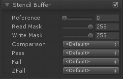
Referencing Custom PropertiesCertain shader options, like Cull Mode or Stencil, can also be configured by shader properties, Ints and Floats to be specific, instead of their usual predefined values.
Shader Functions
Shader Functions, SF for short, are individual node networks that allow you to build reusable functions. Easy to setup and extremely flexible, they work by receiving input values directly from your shader, processing that information and outputting them back for further alterations or direct use. SF assets are not bound to any shader, you can use them multiple times throughout your project, in the same shader, inside other Shader Functions, or even share them with other users. From simple to complex graphs, Shader Functions are a great way to reduce canvas clutter by packing complex networks into single nodes, and a great way to eliminate unnecessary repetitive tasks; they can be considered a form of "grouping", that offers you a way to group nodes into more manageable assets.
Features
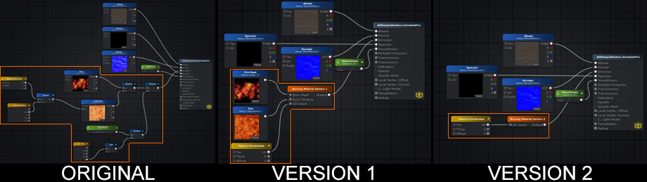
Comparison
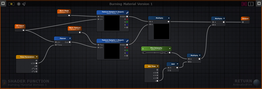
The node networks above all produce the same burning effect. The original version does not use shader functions. Version 1 uses a SF that contains the original node network used to generate the burning effect, it receives 1 Texture Object node for the burn mask, 1 Texture Object node for the fire texture, and 1 Texture Coordinate node. Version 2 is simpler than the previous example, the burn effect generation and texture nodes are all included in the SF, the only exception being the Texture Coordinate node that allows users to tweak its behavior. Keep in mind that a SF does not need to receive any input, the outputted data can be entirely generated in its graph if necessary. Version 1 Shader Function Example
Creation and Usage
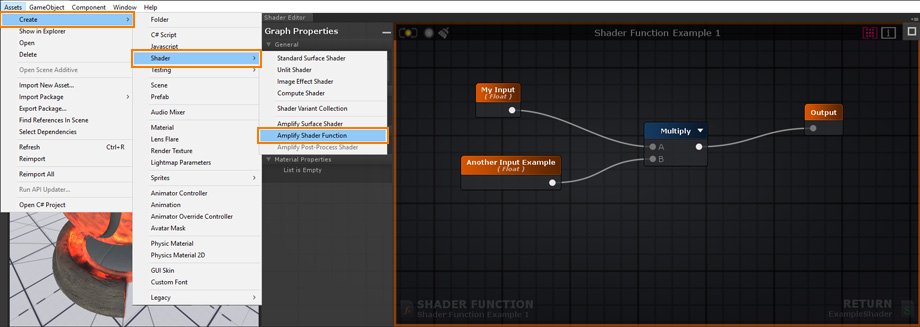
Create a new Shader Function Asset under Assets > Create > Shaders > Amplify Shader Function.
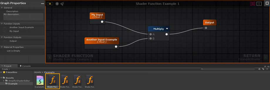
Your newly created Shader Function will be automatically opened in the ASE Editor after being renamed.
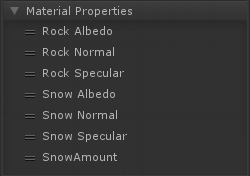
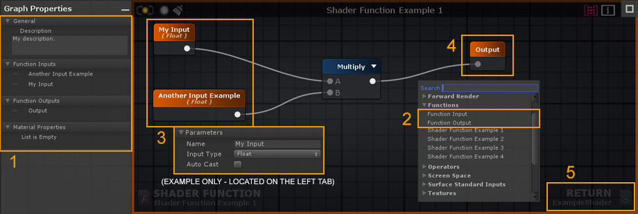
1. Add your Shader Function description here. You can also reorder your Function Inputs/Outputs and Material Properties by dragging them to the desired position. The order set in your SF will be the same used in your Material inspector tab. 2. Create 2 Input nodes or more. By default, there's always 1 Output node but you can add as many as necessary. You can also use other SF nodes inside your active SF but, in order to avoid Shader Function Loops, you cannot add a function to its own canvas. 3. Select an Input node to set the type used or toggle the Auto Cast option to automate the procedure directly in the left tab as you would with any other node properties. 4. Connect your resulting output(s) directly to the Output node(s). 5. Save your changes and click Return to go back to the previously open Shader or Material, if any.
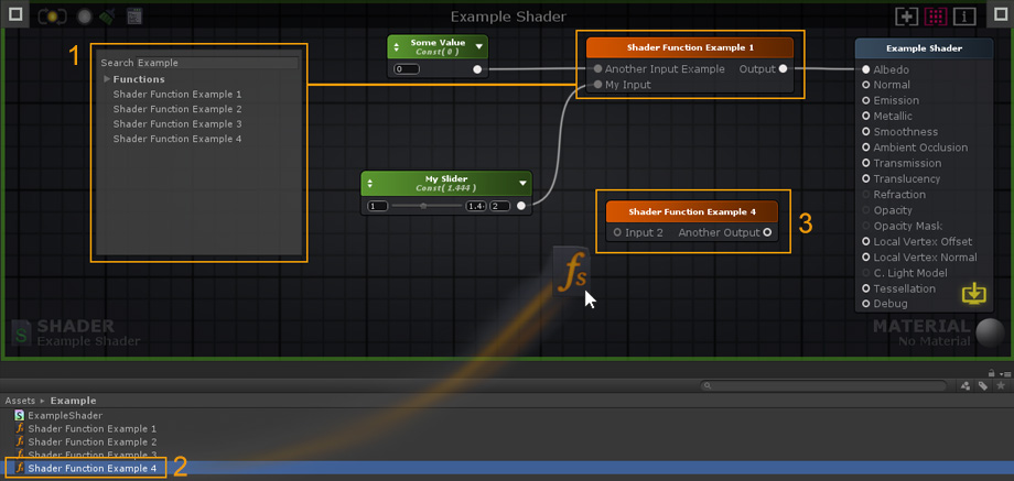
1. Add the created Shader Function to your shader by selecting it directly from the Node List. SF nodes can be used just as any other ASE nodes, they can be duplicated, copied, or deleted. 2. Alternatively, you can drag & drop Shader Functions directly into your editor canvas. 3. Double-click a SF node to open it. HotkeysColored Line Mode
Press [ W ] to toggle it. Node Previews
Press [ P ] to toggle node previews Multi-line Mode Press [ CTRL + W ] to activate the multi-line mode. Full Shortcut ListEditor
Nodes
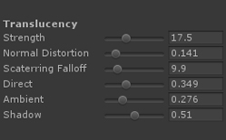
TranslucencyThe Translucency input provides a fast method of representing light scattering. It's not the most realistic method available but it's a flexible and fast-performing approximation. In our example (AmplifyShaderEditor\Examples\Official\Translucency) we use a simple red tinted Depth Texture to represent the skin subsurface scatter effect but you don't necessarily need to use the same setup, you could very well plug a full RGB texture to the Translucency Input in order to get some color variation or stylized results.
Your First shader
1. Open the Editor, create a new material and a new shader in the Project Explorer tab. In the newly created material, select your new shader and click on the Open in Shader Editor button to open both the shader and material.
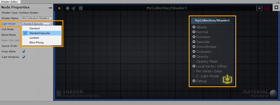
2. As an example, select the Output Node and change its Light Model to specular.
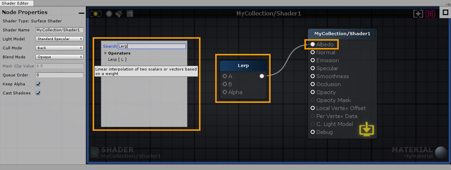
3. Right click on the canvas to open the searchable node list and type “Lerp”. Click on Lerp and connect the node Output Port to the Albedo Input Port.
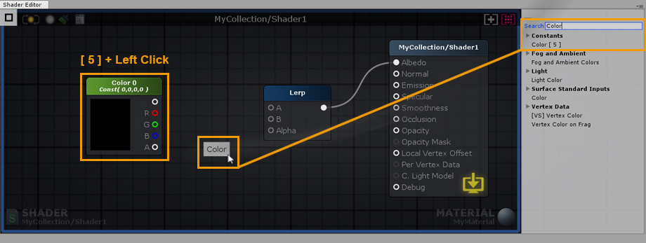
4. Hold the 5 shortcut key and click on the canvas to create a new Color node. Alternatively, you can use the searchable list used early or drag and drop the node from the Node Palette on the right side; Constants > Color [ 5 ].
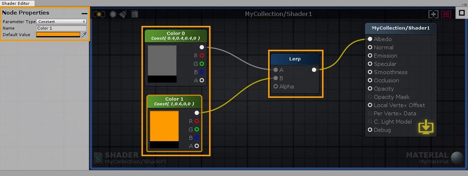
5. Select the new Color node and hit ‘CTRL/CMD+D’ to duplicate it. Connect both nodes to the Lerp Input Ports. Set the first node to gray and the second one to a more lively color.
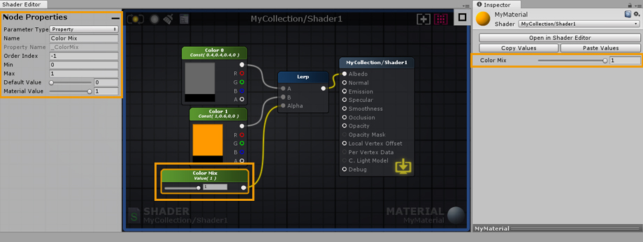
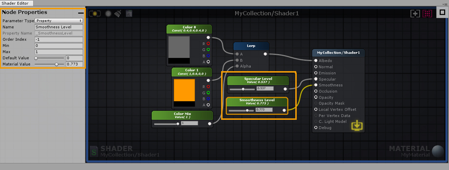
6. Create a Float node by dragging and dropping it from the Node Palette, connect it to the Alpha port of the Lerp node. In the node properties of the newly created float, set its Minimum value to 0 and Maximum to 1. Notice that the Float can now be controlled by a Slider. Don’t forget to set its Parameter Type to Property, this way you will be able to change it directly in the material. You can also name the node and change its position in the material inspector by adjusting the Index value. As an example, lets name it Color Mix.
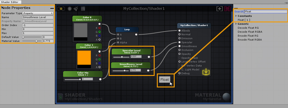
7. Create a new Float and connect it to the Smoothness Input Port of the Output Node, set its Minimum value to 0 and Maximum to 1 as you did before. Set its type to Property and name it Smoothness Value. Create another Float and connect it to the Specular Input Port, set its Minimum value to 0 and Maximum to 1. Set its Type to Property and name it Specular Value.
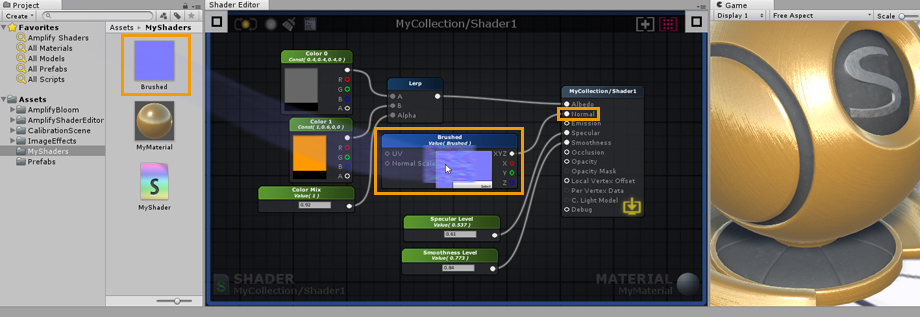
8. To conclude, Drag and Drop a Normal Map texture from your Project Explorer directly into the canvas. As an example, we used a Brushed Metal texture. Connect it to the Normal Input Port of the Output Node and you are done. You have just built your first shader, don’t forget to save your work regularly by clicking the Update button located in the upper left corner. Alternatively, you could edit the shader with the LIVE mode enabled, any change are immediately saved and updated. Depending on the complexity of the shader, the LIVE mode may take a second or so to update. Contrary to Default shader values, any changes made to a material property are immediately visible.
|

3rd-Party Compatibility
Aura 2
Using Aura 2 with ASE is quite simple, just add the necessary nodes.

Be sure to check the official Aura 2 Manual for updated information.
Substance Support
Support for Substances in Unity 2018 and above has been added to ASE.

The original Substance example had to be packaged into a Unity package since .sbsar files now cause an importing error in Unity 2018, as native Substance support has been dropped.
If you're using pre-Unity 2018 versions where native Substance support wasn't yet deprecated, you can find the Substance Example below:
- Go into the AmplifyShaderEditor\Examples\Official\Substance folder
- Extract the LegacySubstanceExample.unitypackage
If you're using Unity 2018, you'll need to make sure that you install the Allegorithmic Substance plugin before you extract the proper ASE package:
- Download, import and setup the Substance in Unity
- Go into the AmplifyShaderEditor\Examples\Official\Substance2018 folder
- Extract the Substance2018.unitypackage
ASE lets you use substances directly or indirectly from within the editor. The most basic way to use a substance is to literally drag and drop a substance asset inside the editor. A new Substance Sample node will be created with it's various textures inside that can be used anywhere.
It's possible to set the substance to generate all textures and drag and drop each one of them independently as a regular texture. These will maintain their reference and update accordingly even if you regenerate the textures.
It's also possible to create a generic shader that is used directly in the shader. The only caveat for this is the extra configuration needed in the substance asset to link each texture sample to a generated texture. If a more automatic process is needed the texture sample node can be set to use a property name that matches Unity's default names (ie: _MainTex for albedos, _SpecGlossMap for specular maps, _MetallicGlossMap for metallic maps, _Glossiness for smoothness maps, _BumpMap for normal maps, _OcclusionMap for occlusion maps, _EmissionMap for emission maps, etc) This way the substance asset will detect the property and automatically assign them the correct texture without extra intervention.
MegaSplat
Native support for ASE is included in MegaSplat
Curved World Shaders
This guide will show you how to integrate Curved World with the Amplify Shader Editor.
You may download a simple example here.
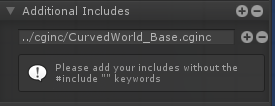
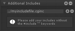
1. For the first step, we're going to include the curvedworld.cginc file. In the image above, notice how we added the include with the string: "../cginc/CurvedWorld_Base.cginc", this is because our shader file was in a folder next to the cginc folder where the file is, so the "../" part of the string goes up one folder, the "/cginc/" part looks inside the cginc folder and the last part is the file itself. You could simply use "CurvedWorld_Base.cginc" IF your shader file was next to this file.
Note: You have to be careful with this inclusion because Unity doesn't let you automatically detect where the file is by name, you have to specify the file path. If you happen to move the file to a different folder you have to fix the file path and recompile the shader again or else it will fail to include the file. (Alternatively you can also use a project based absolute path: "Assets/VacuumShaders/Curved World/Shaders/cginc/CurvedWorld_Base.cginc". In this case you will only have to fix the path in case you move the Curved World Shader folder.)'
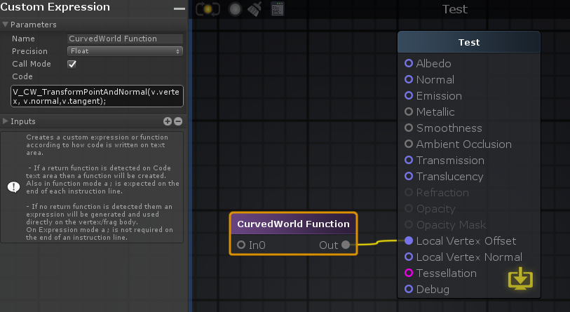
2. Secondly, in order to apply the curved world effect to the object with your shader, you need to call its own Function, which is within the file we included in the first step. To achieve this, you must create and connect a custom expression node into the "local vertex offset" output and have it call the Function you want to call in the code box, which in this case is "V_CW_TransformPointAndNormal(v.vertex, v.normal,v.tangent);". Notice the "Call Mode" checkbox in the parameters panel, it needs to be toggled on in order for this step to work without any issues.
Note: Should you need to do some vertex transformation, you can still connect it to the input of the Function node.
That's it! Now you can use everything else like you would in a normal ASE shader and it should work in curved world!
VertExmotion
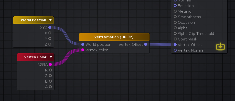
The VertExmotion package includes built-in nodes for ASE. Be sure that the shader name begins with "VertExmotion/", followed by your shader name, else it wont be recognized as being compatible.
1.Unpack the file 'VertExmotion/Addon/VertExmotion_AmplifyShaderEditorNodes.unitypackage'.
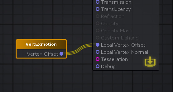
2. Add the VertExmotion node and connect it to the Local Vertex Offset Input port.
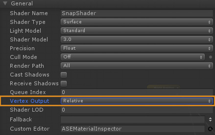
3. Set the Vertex Output to 'Relative' in the Output Node parameters.
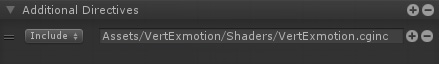
4. Add the VertExmotion cginc file (Assets/VertExmotion/Shaders/VertExmotion.cginc) under Additional Directives, Includes.
5. If you're using tessellation, be sure to add the VertExmotion (Advanced NC) node; plug both the Vertex Offset and Normal to the Output Node inputs. (Optional)
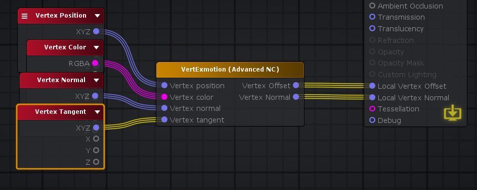
6. HD SRP variant included. (Optional)
General Tips
Mobile Shaders
When creating shaders for mobile there are some special considerations to take into account. Usually these considerations are tied to the performance of the shader but sometimes there are artistic or design choices that lead to modifications that are needed at the shader level.
These are just the most common way you may find useful to create shaders for mobile:
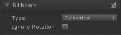
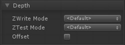
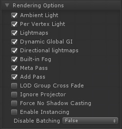
Rendering Options
Often overlooked, rendering options let you turn off some key feature of unity lighting system. For example, you may find to be enough for your purpose to turn off Unity GI system but still maintaining their PBR workflow.
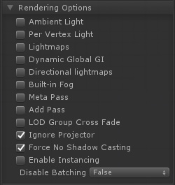
It this image extreme example every special lighting feature is turned off and even shadows are off. This might not be what what's needed, but it's a good starting point.
Custom Lighting Model
Attention Custom Lighting is only available for the Universal and Built-in Renderer. Universal Custom Lighting has specific requirements which make use of the "SRP Additional Light" Node, please check this stream and example files for additional details: Dev Stream #4 - Outline Toon Shading in LW/URP
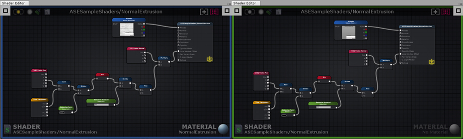
ASE allows the creation of custom lighting model shaders for the built-in renderer. These are still unity surface shaders that allow the replacement of unity lighting functions. In ASE this means you can set your shader Light Model into custom lighting. Doing this will transform the main output node into one that only has emission and opacity ports. With this it's possible to use existing nodes with some extra light nodes to create an optimized and tailor fitted shader for a specific purpose.
The following image shows how it's possible to create a simple wrapped Lambertian shader which should be very performant for lower end machines.
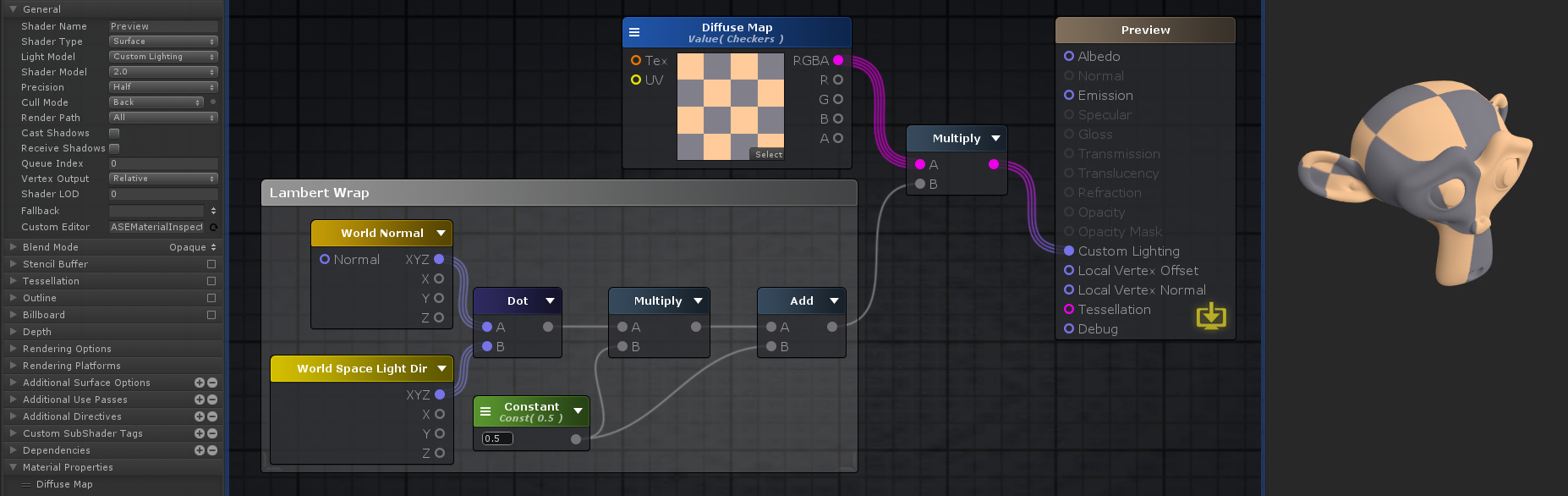 Nodes used:
Texture Sample,
World Normal,
World Space Light Dir,
Dot,
Multiply
Float,
Add
Nodes used:
Texture Sample,
World Normal,
World Space Light Dir,
Dot,
Multiply
Float,
Add
Combine this with the previous rendering options for extra savings and do notice how in the general options a few of them where turned off or down for better performance (ie: Shader Model, Precision, Cast Shadows)
As a learning step, it might be a good idea to check the Toon Ramp sample provided by the ASE package which uses custom lighting in a more complex way to create a toon ramp effect with rim light and shadow support.
Mobile Friendly Templates
Some times what's needed is a specific vertex/frag shader that does a very simple job, for instance, particles, sprites, UI, etc. For these cases and others ASE allows the injection of shader code into pre-existing shaders that we call "templates". These are regular vertex/frag shaders that were modified by adding some tags the editor can read to know where to inject new code and what code already exists in the template.
There's a whole page dedicated on how these templates work and how you can build your own right here.
The reason they might be important for mobile shaders is that these templates can be extremely simple with barely any code at all. If the idea is to save performance, a generic unlit template can serve as a base to build upon since these are editable inside the editor and extra features can be added either by construction a more complex graph tree or by editing the original template. The only caveat being the user must have a bit of shader knowledge to edit or create the original template shader. Fortunately ASE already provides a few templates that any user can pick and use as any other shader.
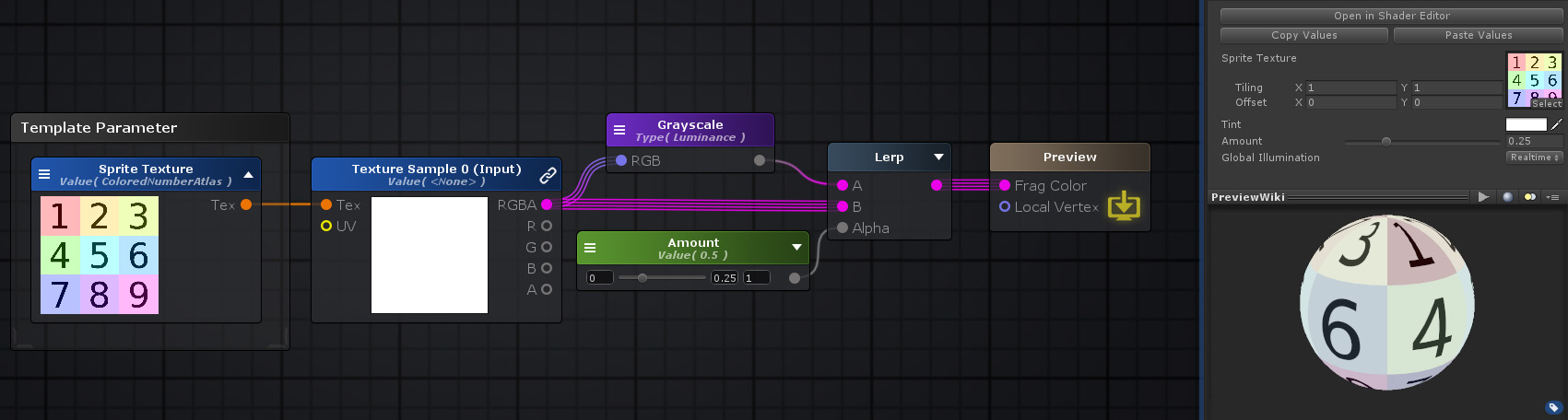 Nodes used:
Template Parameter,
Texture Sample,
Grayscale,
Float,
Lerp
Nodes used:
Template Parameter,
Texture Sample,
Grayscale,
Float,
Lerp
This feature is still in development and more of these templates will be provided in the future to implement more complex or specific effects when they become available.
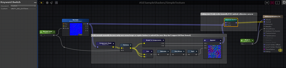
Android
When using the Texture Sampler node in ASE and the target platform is Android, it will ignore the Scale Parameter, which is an intended behaviour because Unity does not scale normal maps for platforms that don't support DXT5nm format, which is the format Unity compresses normal maps into.
Although this can be fixed by directly changing the built-in shader files, which is troublesome to do and to maintain, a simpler solution would be to do the exact same calculation that Unity does withing the editor itself.
The following image and shader file perform this calculation while also making sure that the shader still works even outside of the Android environment by checking the define symbol that Unity sets itself. We recommend that you create a Shader Function with this logic if you need to use it in several shaders.