Unity Products:Amplify Shader Editor/Parallax Occlusion Mapping
Samples
The ASE package includes several Parallax samples, be sure to check them out.
- AmplifyShaderEditor\Examples\Official\ParallaxMapping
- AmplifyShaderEditor\Examples\Official\ParallaxOcclusionMappingPOM
- AmplifyShaderEditor\Examples\Official\ParallaxOffsetFakeInterior
About
Parallax occlusion mapping (POM) is an enhancement of the Parallax Mapping technique. Parallax occlusion mapping is used to procedurally create 3D definition in textured surfaces, using a displacement map (similar to a topography map) instead of through the generation of new geometry.[Reference]
Node
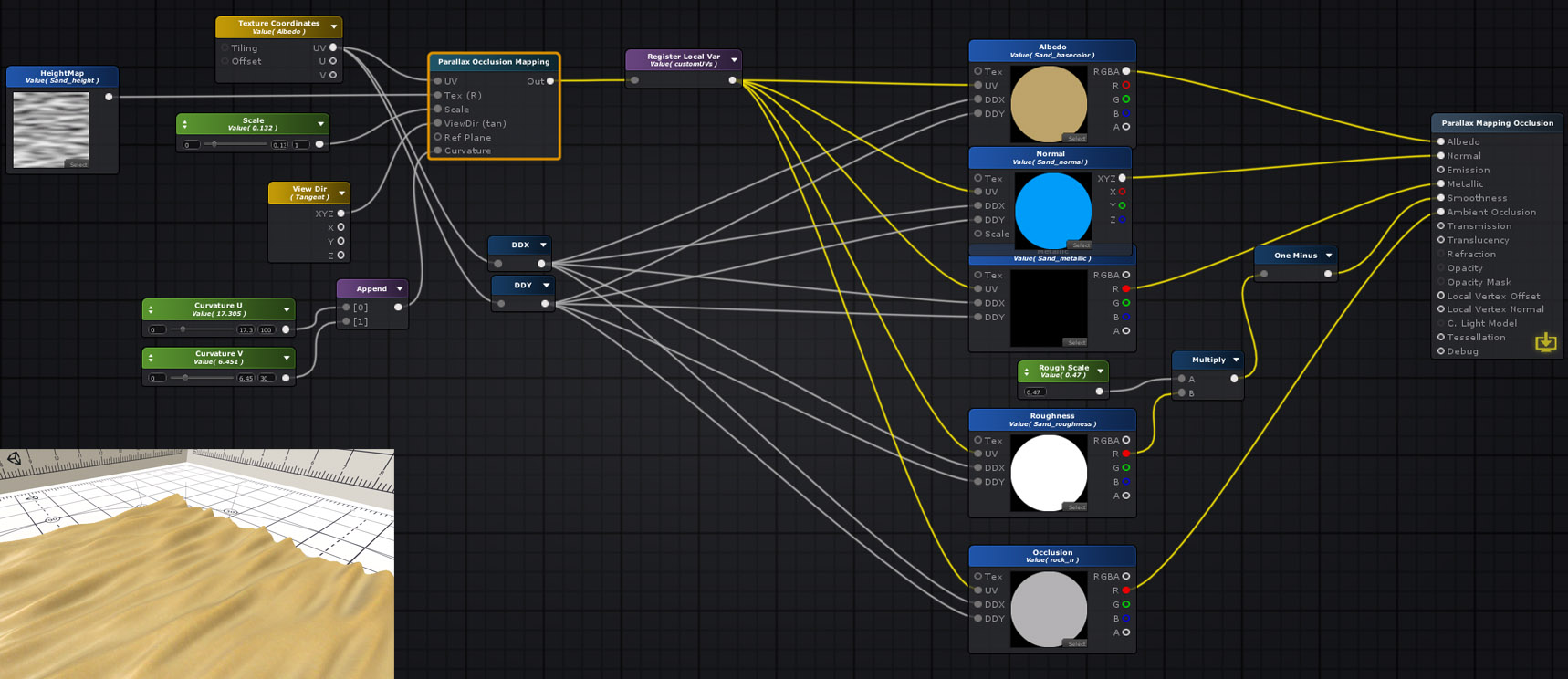
The Parallax Occlusion Mapping node calculates the offseted UVs for the parallax occlusion mapping effect. Similarly to the Parallax Mapping node, you must plug the output to the UV Input Port of all channels (Albedo, Normal etc) in order to ensure that the effect is properly displayed. In addition to the Parallax Occlusion Mapping node, you must specify your own derivatives for texture lookups, be sure to set the Mip Mode Texture Sample node to Derivative.
When sampling textures, we must be careful about how to specify derivatives for texture lookups. In general, the displaced texture coordinates have discontinuities (for example, due to sections of the texture that are occluded). When mipmapping or anisotropic filtering is enabled, the GPU needs information about the derivatives of the texture coordinates. Because the GPU approximates derivatives with finite differences, these derivatives have incorrect values at discontinuities. This leads to an incorrect choice of mipmap levels, which in turn leads to visible seams around discontinuities. Instead of using the derivatives of the displaced texture coordinates, we substitute the derivatives of the base texture coordinates. This works because displaced texture coordinates are always continuous, and they vary at approximately the same rate as the base texture coordinates.[Reference]
|
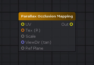
Input
Output
|
 |
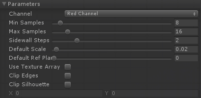
Node Properties
|
 |
Additional Nodes
Be sure to use the DDX and DDY nodes along with the Texture Coordinates node used for the calculations, it's the quickest way to get the approximate partial derivatives needed for the Parallax Occlusion Mapping effect.
Example