Unity Products:Amplify Shader Editor/Templates
Product Page - Samples - Manual - Scriptable Rendering Pipeline - Shader Functions - Templates - Post Processing Stack - Tutorials - API - Nodes - Shader Graph to ASE - Community Nodes
Templates Description
Introduction
This feature allows users to create an ASE shader from an already existing one which will be used as base, or Template.
Templates are regular Unity shaders with special ASE tags placed on key points. These tags are written as comments so they don't affect the shader compilation and its default behavior.
Any shader can be converted to a template and, if the given shader has multiple passes, each one is represented by its own Output node.
How to use
Create a Shader
Creating an ASE shader using templates is as easy as creating a regular surface one. Hit the right mouse button on the project view, select Create > Amplify Shader and from that menu a list with the default ASE Surface Shader is shown followed with all the available templates.
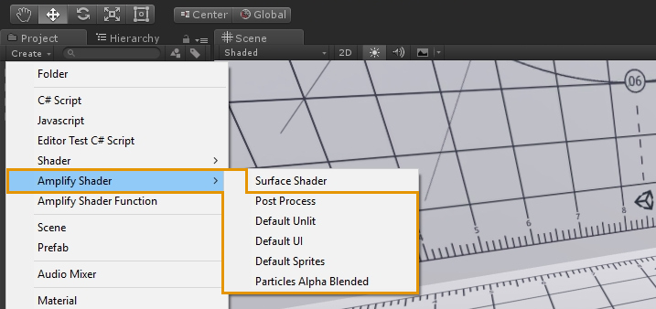
As for now, the available templates are:
- Post-Process
- Default Unlit
- Default UI
- Default Sprites
- Particles Alpha-Blended
A user can, at any time, swap which template is being currently used and also go back to the default Surface Shader. This is done by hitting the Shader Type drop down on the current Output Node property window.
Options available at the Output node are determined on what was made available to modify over the template.
Check Template Source Code
A user can, at any time, hit the Edit Template button on the Output Node properties window to check the source code of the current template.
Please note that, as for now, ASE only loads a template's info on its startup, so any changes on the template require the user to restart the plugin to take effect on your shader's next compilation.
This limitation will be addressed in a future update.
Template Nodes
New nodes were added in order to get access to specific template data from inside the graph.
Templates Parameters
A new Template Parameter node is also available now. It gives you access to Properties and Global Variables available on the current template.
Simply hit the Parameter drop down on its Node Properties window, or on the upper left corner of the nodes body to choose which Property/Global Variable to use. When selecting a parameter it will let you know if a Property or a Global Variable is selected.
Multiple Templates Parameter nodes can be placed across the shader graph, each one with the same or different selected parameters.
Please note that previews for this node are only available when on Material mode and for Property type parameters.
Templates Vertex and Fragment Data
Similar to Template Parameters, Amplify Shader Editor also allows direct access to Vertex and Interpolated data.
The Vertex Data node allows users to get direct access to vertex data declared over the structure set over the vertex shader body on the template.
Likewise the Fragment Data node allows user to get direct access to fragment data declared over the interpolator structure on the template which will be sent into the fragment function.
Template Local Var Data
Local variables declared on the template can now be accessed over the shader graph via the Template Local Var Data node. Only local variables preceded with the /*ase_local_var*/tag over its declaration will be caught and made available over the graph.
The user can specify what type of local variable is being declared so ASE nodes can use them as well.
For that the local variable tag declaration is as it follows:
/*ase_local_var:Variable Type*/
Variable Type can be one the values below:
- p: Vertex Position
- n: Vertex Normal
- t: Vertex Tangent
- c: Vertex Color
- sp: Clip Position
- spu: Screen position
- spn: Normalize Screen Position
- uv0: Texture coordinates 0
- uv1: Texture coordinates 1
- uv2: Texture coordinates 2
- uv3: Texture coordinates 3
- uv4: Texture coordinates 4
- uv5: Texture coordinates 5
- uv6: Texture coordinates 6
- uv7: Texture coordinates 7
- wn: World Normal
- wt: World Tangent
- wbt: World Bitangent
- wvd: World View Dir
- wp: World Position
- rwp: relative World Position
- vf: VFace
- sc: Shadow Coods
P.e. if the a local variable is declared this way:
/*ase_local_var:spn*/ float2 screenUVs = (...);
Then the Screen Position node will use as well to return normalized screen position.
Create your own template
The process of converting a shader into a Template is quite straightforward.
Single Pass Example
Here's a simple example of a single pass unlit vertex/frag shader converted to an ASE Template.
Shader /*ase_name*/ "ASETemplateShaders/DefaultUnlit" /*end*/
{
	Properties
	{
		_MainTex ("Sprite Texture", 2D) = "white" {}
		_Color ("Tint", Color) = (1,1,1,1)
		/*ase_props*/
	}

	SubShader
	{
		Tags { "RenderType"="Opaque" }
		LOD 100
		Cull Off
		/*ase_pass*/

		Pass
		{
			CGPROGRAM
			#pragma target 3.0
			#pragma vertex vert
			#pragma fragment frag
			#include "UnityCG.cginc"
			/*ase_pragma*/

			struct appdata
			{
				float4 vertex : POSITION;
				float4 texcoord : TEXCOORD0;
				float4 texcoord1 : TEXCOORD1;
				/*ase_vdata:p=p;uv0=tc0.xy;uv1=tc1.xy*/
			};

			struct v2f
			{
				float4 vertex : SV_POSITION;
				float4 texcoord : TEXCOORD0;
				/*ase_interp(1,7):sp=sp.xyzw;uv0=tc0.xy;uv1=tc0.zw*/
			};

			uniform sampler2D _MainTex;
			uniform fixed4 _Color;
			/*ase_globals*/

			v2f vert ( appdata v /*ase_vert_input*/)
			{
				v2f o;
				o.texcoord.xy = v.texcoord.xy;
				o.texcoord.zw = v.texcoord1.xy;

				// ase common template code
				/*ase_vert_code:v=appdata;o=v2f*/

				o.vertex.xyz += /*ase_vert_out:Local Vertex;Float3*/ float3(0,0,0) /*end*/;
				o.vertex = UnityObjectToClipPos(v.vertex);
				return o;
			}

			fixed4 frag (v2f i /*ase_frag_input*/) : SV_Target
			{
				fixed4 myColorVar;
				// ase common template code
				/*ase_frag_code:i=v2f*/

				myColorVar = /*ase_frag_out:Frag Color;Float4*/fixed4(1,0,0,1)/*end*/;
				return myColorVar;
			}
			ENDCG
		}
	}
}
Available Tags
As can be noted, there are a couple of ASE tags scattered across the shader code. Here's a brief explanation of all the available tags:
ase_name
This tag is extremely important since it's the one which lets ASE know this shader needs to be analysed as a Template. It also shows where ASE can inject a new custom shader name.
Shader /*ase_name*/ "ASETemplateShaders/DefaultUnlit" /*end*/
The string between ase_name and end is used as the default name when a new shader is created using this template.
ase_props
This tag specifies both where the current shader properties are and where ASE can inject new ones. Only properties declared before the tag are read and made available to the user.
On this template, two properties will be detected and registered, Sprite Texture and Tint.
ase_main_pass
This tag is specific to multi-pass effects and let ASE to now which pass is the main one. Please check the Multi-Pass section for additional information.
ase_hide_pass
This tag is specific to multi-pass effects and allows passes to be hidden, or completely excluded from being modified. Please check the Excludind/Hidding Passes section for additional information.
ase_tags
This tag specifies where ASE can inject new shader tags/parameters.
LEGACY: The /*ase_tag*/ tag is no longer used on ASE version v1.4.5 or newer since the template can automatically figure out where they are.
ase_pass
This tag specifies where ASE can inject new passes and/or states setup. This is necessary for nodes like Grab Screen Color, where a Grab Pass needs to be declared on the shader.
LEGACY: The /*ase_pass*/ tag is optional on ASE version v1.4.5 or newer since the template can automatically figure out where to place the Grab Pass declaration.
ase_pass_end
This tag should be used only on multi-pass templates after the end of the subshader's last pass. This tags helps ASE parser to know where the last pass end so all passes can be correctly excluded (if requested) on the generated shader.
ase_pragma
This tag specifies where ASE can inject new pragma directives and include files. Multiple important nodes like Texture Sampler require this tag to work since they internally use Unity functions from its library.
Besides internal usage by the referred nodes, the /*ase_pragma*/ is also used to add new #defines, #includes and #pragmas explicitly declared on the Additional Defines, Additional Includes and Additional Pragmas subsection on Pass section of the Output node.
We heavily encourage this tag to be declared BEFORE the /*ase_globals*/ tag.
ase_vdata
This tag specifies where vertex data is declared and where to add new one. It must be set at the final of the vertex data struct.
It's also responsible for letting ASE know which type of data each element contains."
On this example,
/*ase_vdata:p=p;uv0=tc0.xy;uv1=tc1.xy*/
Three elements are declared on the struct.
float4 vertex : POSITION;
float4 texcoord : TEXCOORD0;
float4 texcoord1 : TEXCOORD1;
For the POSITION, semantic data sent is usually a vertex position but semantics like COLOR or TEXCOORD# can be used for a lot of different purposes.
Each data type is declared via Data Type = Semantic shortcut using a ; as a separator between declarations.
Here are all the data types:
| Data Type | Description |
|---|---|
| p | Local Vertex Position |
| sp | Clip Space Position |
| c | Color |
| n | Normal |
| t | Tangent |
| uv# | UV Coordinates # |
| Shortcut | Semantic |
|---|---|
| p | POSITION |
| sp | SV_POSITION |
| c | COLOR |
| n | NORMAL |
| t | TANGENT |
| tc# | TEXCOORD0# |
Looking at how this tag was declared, we can see the following info:
- p=p: POSITION semantic variable contains local vertex position
- uv0=tc0.xy: TEXCOORD0 semantic variable, most specifically its x and y component, contains UV set 0
- uv1=tc1.xy: TEXCOORD0 semantic variable, most specifically its x and y component, contains UV set 1
ase_interp
This tag is quite similar to ase_vdata on how it's declared but it now lets ASE know where the interpolators struct is being declared.
It also must be set at the final of the interpolators data struct and is responsible for letting ASE know which type of data each element contains.
An additional step is required, where interpolators that can be used by ASE must be explicitly declared on the tag.
This is done via the current syntax ase_interp(Min,Max). All interpolators between Min and Max , [ TEXCOORD#MIN - TEXCOORD#MAX ] are considered available to be used. Please note that Min may be not be a full interpolator but only part of it.
E.g. if x and y of TEXCOORD1 is being used, you can declare the tag like this ase_interp(1.zw,7). This way TEXCOORD1 can be used by ASE, but only the z and w channels.
So, on this example,
/*ase_interp(1,7):sp=sp.xyzw;uv0=tc0.xy;uv1=tc0.zw*/
two elements are declared on the struct.
float4 vertex : SV_POSITION;
float4 texcoord : TEXCOORD0;
We can see the following info set on the tag.
- ase_interp(1,7): Interpolators between TEXCOORD1 and TEXCOORD7 are available
- sp=sp.xyzw: SV_POSITION semantic variable contains Clip Space Position
- uv0=tc0.xy: TEXCOORD0 semantic variable contains UV Set 0 on its xy components
- uv1=tc0.zw: TEXCOORD0 semantic variable contains UV Set 1 on its xy components
Also, besides the usual interpolated data, some specific data can also be marked as available over the interpolators.
| Data Type | Description |
|---|---|
| wn | World Normal |
| wt | World Tangent |
| wbt | World Bitangent |
| wvd | World View Dir |
| wp | World Position |
ase_globals
This tag is similar to ase_props and specify both where current global variables are and where ASE can inject new ones. Only declared global variables before the tag are read and made available to the user.
On this template, two global variables will be detected _MainTex and _Color. Since these global variables are associated to properties they will not be registered since this already was done by the ase_props tag.
ase_funcs
By default ASE places all functions used on the shader after global variable declaration over the /*ase_globals*/. By setting this optional tag it lets ASE know that its default behavior should be ignored and functions should be placed over the /*ase_funcs*/ tag.
ase_vert_input
This tag defines where the vertex function input parameters are located so ASE can add additional parameters if needed. E.g. Switch By Face node requires a VFACE type variable to be declared as input.
ase_vert_code
This tag defines where ASE can insert additional vertex code created by vertex input ports on the graph.
Two additional parameters need to be defined, the first specifies the type and name of the function input parameter while the second defines the type and name of the output/return parameter.
/*ase_vert_code:v=appdata;o=v2f*/
- v=appdata: Vertex data received from variable v of type appdata
- o=v2f: Return output variable o of type v2f
ase_vert_out
This tag defines major code injection points inside the vertex body. These points are transformed into Vertex Input ports on the Output Node.
Port Name and Port Type are defined inside the tag as the first and second of its parameters. On this current example a port of name Local vertex and type Float3/Vector3 is going to be created.
The tag must be placed inside a variable operation and encompasses the operation itself. This variable must then used by the original template code.
On this example,
o.vertex.xyz += /*ase_vert_out:Local Vertex;Float3*/ float3(0,0,0) /*end*/
The tag can modify o.vertex and this way add an offset to it. If no node is connected to that input port then the original operation is maintained.
ase_frag_input
This tag is similar to ase_vert_input but it defines where the fragment function input parameters are located so ASE can add additional parameters if needed.
ase_frag_code
This tag is similar to ase_vert_code and defines where ASE can insert additional fragment code created by fragment input ports on the graph.
However, only one parameter is defined on this tag, since a fragment always returns a color. This parameter specifies the type and name of the interpolator parameter.<br/
/*ase_frag_code:i=v2f*/
- i=v2f: Interpolator variable i of type v2f
ase_frag_out
This tag is similar to ase_vert_out but it defines major code injection points inside the fragment body. These points are transformed into Fragment Input ports on the Output Node.
Port Name and Port Type are defined inside the tag as the first and second of its parameters. On this current example a port of name Frag Color and type Float4/Vector4 is going to be created.
The tag must be placed inside a variable operation and must encompass a default operation. This variable must then be used in some manner by the original template code.
On this example:
myColorVar = /*ase_frag_out:Frag Color;Float4*/fixed4(1,0,0,1)/*end*/
The tag can modify the myColorVar in order to modify the final fragment color.
If no node is connected to the input port then the original operation is maintained.
ase_dependencies_list
Allow adding shader dependencies when using this template. The dependencies list will replace the tag when creating the final shader.
Subshader/Pass Render State Options
For a specific render state option ( p.e.Cull Mode ) to be available for modification over the canvas, it must first be declared on the template. No special tags are needed for it to be correctly captured.
Options which are declared inside a Pass scope are set as Pass Properties and will be accessible on the Pass section on the output node. Options which are declared on a sub-shader scope before all its passes will be set as Sub-Shader properties and will be made available on the Sub-Shader section of the Output node.
Render State Options that are currently being captured by the template are:
- Blend Mode
- Blend Operation
- Cull Mode
- Color Mask
- Stencil Operation
- ZTest Mode
- ZWrite Mode
- Depth Offset
- Sub-Shader/Pass Tags
- Shader Model
Sub-Shader LOD is also being captured but is not editable from the ASE graph.
Here is each render state option displayed for the current example.

As can be seen over the SubShader template source, Render Tags and Cull Mode are declared, so they are made available at the SubShader section on the output node.
On the Pass code only Shader Model is declared so it will the only one available at the Pass section.
Since Stencil Buffer operation cannot be defined on a disabled state, the tag /*ase_stencil*/ was created to let users be able to add the stencil option into their templates.
Stencil operations are disabled by default when first setting this template to a shader.
An /*ase_all_modules*/ tag was also created to, instead of manually adding all properties, automatically enables all the following options into the Subshader/Pass properties.
- Blend
- Cull Mode
- Color Mask
- Stencil
- Depth
- Shader Model
Please note that if any of these properties is already defined over the SubShader/Pass then their original definition will be used.
Multi-Pass
Some extra considerations must be taken when creating multi-pass templates.
Setting Main Output node
A main Output node must be selected since multiple ones are created ( one per pass ) on a multi-pass shader. This selected output will internally command all others among other things. By default if nothing is specified, the Output node representing Sub-Shader 0 Pass 0 will set as the main Output node, but the user can manually select another one by declaring the /*ase_main_pass*/ tag inside of the intended pass.
Linking Pass/Output node ports
There may be situations on which a user will always need a result/sub graph to be shared across similar input ports from different passes. This can be done by internally linking these input ports through the assignment of a link Id to each of the input ports configuration over the template. The input port will only appear on the pass which is marked as the main output node or, if none is marked, the first one which declares the link id.
P.e. take a look at this input port configuration:
myColorVar = /*ase_frag_out:Frag Color (2);Float4;_MainColor*/fixed4 ( 0,0,1,1 )/*end*/;
The _MainColor parameter is the link id set for this particular fragment input port.
Although the sub graph will be connected to only a main port, its code will be generated to each specific linked port.
Excluding/Hidding Passes
Passes can be completely excluded from being modified on ASE or simply be on hidden state.
For a pass to be excluded, the /*ase_hide_pass*/ tag must be set over its body and no vertex or fragment data entry points can be declared. This way the Pass body will be copied from the template to the final resulting shader.
An hidden pass is one which is not visible over the canvas but new code can be injected on it. This is done by not only applying the /*ase_hide_pass*/ tag but also declaring data entry points as linked ports. This way the graph connected to the main link port will also be analyzed to each one of the ports on the invisible pass.
Template Multi-Pass Switch
Template Multi-Pass Switch is a node specific to multi-pass shaders as it relays, in compile time, the input port data corresponding to the current pass being analyzed over its output.
Multi Pass Example
Let's extend the previous example to make use of multiple passes and create an outline shader template.
We'll mostly focus only on explaining the specific tags and behaviors of multi-pass templates
Shader /*ase_name*/ "WikiExamples/Simple Multi Pass Outline" /*end*/
{
	Properties
	{
		_OutlineWidth( "Outline Width", Float ) = 0.1
		_OutlineColor( "Outline Color", Color ) = (0,0,0,1)
		_MainBodyColor ( "Main Body Color", Color ) = ( 0,0,0,1 )
		/*ase_props*/
	}

	SubShader
	{
		Tags{ "RenderType" = "Opaque" }

		Pass
		{
			Cull Front
			Blend Off

			Name "Outline"
			CGPROGRAM
			#pragma target 3.0
			#pragma vertex vert
			#pragma fragment frag
			#include "UnityCG.cginc"
			/*ase_pragma*/

			struct appdata
			{
				float4 vertex : POSITION;
				float3 normal : NORMAL;
				float4 texcoord : TEXCOORD0;
				UNITY_VERTEX_INPUT_INSTANCE_ID
				/*ase_vdata:p=p;n=n;uv0=tc0.xy*/
			};

			struct v2f
			{
				float4 vertex : SV_POSITION;
				float4 texcoord : TEXCOORD0;
				UNITY_VERTEX_OUTPUT_STEREO
				/*ase_interp(0.zw,7):sp=sp.xyzw;uv0=tc0.xy*/
			};

			uniform float4 _OutlineColor;
			uniform float _OutlineWidth;
			/*ase_globals*/

			v2f vert ( appdata v /*ase_vert_input*/ )
			{
				v2f o;
				UNITY_SETUP_INSTANCE_ID ( v );
				UNITY_INITIALIZE_VERTEX_OUTPUT_STEREO ( o );
				o.texcoord.xy = v.texcoord.xy;
				o.texcoord.zw = 0;
				/*ase_local_var*/float3 MyLocalVar;
				/*ase_vert_code:v=appdata;o=v2f*/
				v.vertex.xyz += /*ase_vert_out:Vertex Offset;Float3*/ v.normal*_OutlineWidth /*end*/;
				o.vertex = UnityObjectToClipPos ( v.vertex );
				return o;
			}

			fixed4 frag ( v2f i /*ase_frag_input*/ ) : SV_Target
			{
				fixed4 myColorVar;
				/*ase_frag_code:i=v2f*/
				myColorVar = /*ase_frag_out:Color;Float4*/_OutlineColor/*end*/;
				return myColorVar;
			}
			ENDCG
		}

		Pass
		{
			/*ase_main_pass*/
			Cull Back
			Blend Off

			Name "MainBody"
			CGPROGRAM
			#pragma target 3.0
			#pragma vertex vert
			#pragma fragment frag
			#include "UnityCG.cginc"
			/*ase_pragma*/

			struct appdata
			{
				float4 vertex : POSITION;
				float4 texcoord : TEXCOORD0;
				UNITY_VERTEX_INPUT_INSTANCE_ID
				/*ase_vdata:p=p;uv0=tc0.xy*/
			};

			struct v2f
			{
				float4 vertex : SV_POSITION;
				float4 texcoord : TEXCOORD0;
				UNITY_VERTEX_OUTPUT_STEREO
				/*ase_interp(0.zw,7):sp=sp.xyzw;uv0=tc0.xy*/
			};
			uniform float4 _MainBodyColor;
			/*ase_globals*/

			v2f vert ( appdata v /*ase_vert_input*/ )
			{
				v2f o;
				UNITY_SETUP_INSTANCE_ID ( v );
				UNITY_INITIALIZE_VERTEX_OUTPUT_STEREO ( o );
				o.texcoord.xy = v.texcoord.xy;
				o.texcoord.zw = 0;
				/*ase_vert_code:v=appdata;o=v2f*/
				v.vertex.xyz += /*ase_vert_out:Vertex Offset;Float3*/ float3( 0,0,0 ) /*end*/;
				o.vertex = UnityObjectToClipPos ( v.vertex );
				return o;
			}

			fixed4 frag ( v2f i /*ase_frag_input*/ ) : SV_Target
			{
				fixed4 myColorVar;
				/*ase_frag_code:i=v2f*/
				myColorVar = /*ase_frag_out:Color;Float4*/_MainBodyColor/*end*/;
				return myColorVar;
			}
			ENDCG
		}
		/*ase_pass_end*/
	}
	CustomEditor "ASEMaterialInspector"
}
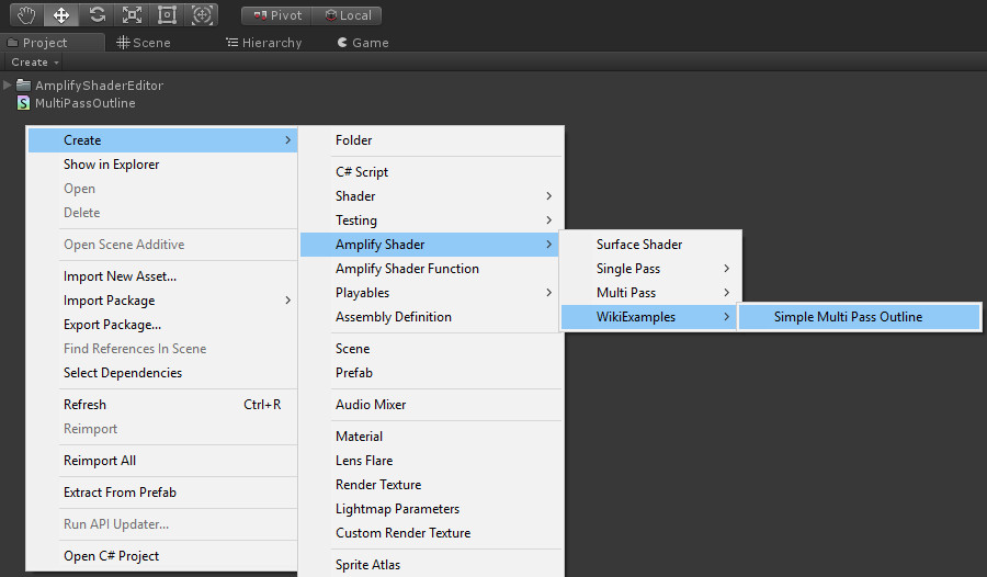
Shader Name
First and foremost please notice the template shader name which is between the /*ase_name*/ and /*end*/ tags. This not only determines the shader default name but also how it is presented on the create menu and Shader Type dropdown. So the WikiExamples/Simple Multi Pass Outline will be translated to this over the Create menu item:
Output Nodes Amount
Here's a newly created shader using this template:
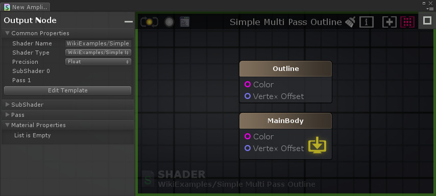
Like stated before, each pass will be represented by its own output node. There are two passes declared over this template so, two output nodes will be created.
Each output node name is set by the respective pass name. For the first pass we can see its name declared via the Name "Outline":
Pass
{
	Cull Front
	Blend Off

	Name "Outline"
	(...)
}
As for the second pass its name is declared via the Name "MainBody" line.
Pass
{
	/*ase_main_pass*/
	Cull Back
	Blend Off

	Name "MainBody"
	(...)
}
If no name is set then an internal name is generated, p.e. SubShader 0 Pass 0, SubShader 0 Pass 1 and so on.
Main Output
Although multiple output nodes are created, one must be assigned to be the main one ( and rule them all ). This is visually represented by the  icon.
icon.
Going back to the Main Body template source shown right above, we can see the /*ase_main_pass*/ tag. This lets ASE know Main Body output was selected to be the main one.
Linking Ports
For demonstration purposes, lets link both Color ports. In order to achieve this, on the first pass we'll replace the fragment Color declaration:
myColorVar = /*ase_frag_out:Color;Float4*/_OutlineColor/*end*/;
by:
myColorVar = /*ase_frag_out:Color;Float4;_Color*/_OutlineColor/*end*/;
Also on second pass we'll replace:
myColorVar = /*ase_frag_out:Color;Float4;*/fixed4 ( 1,1,1,1 )/*end*/;
by:
myColorVar = /*ase_frag_out:Color;Float4;_Color*/fixed4 ( 1,1,1,1 )/*end*/;
Each Color input port now shares the _Color Id and lets ASE know they are linked. Notice that it will disappear from the Outline output node.

Now the graph connected to the Main Body's Color port will also be shared to an invisible Color port on the Outline node.
Under the Hood
Let's take a closer look at a compiled shader using templates and compare it with its selected template. A simple example was created for demonstration purposes using the Unlit Template explained on Single Pass example.
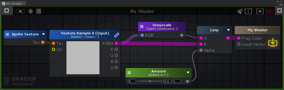
On this simple shader, a color is being fetched from the already existing 2D Sampler template property and a luminance value is being calculated from it. A lerp is then applied between the luminance value and the original color using a newly created Float property called Amount as the interpolator.
Here's the final result after compiling the shader. Template original source code is presented on the left and compiled shader is on the right.

- The usual Made with Amplify Shader Editor header is placed and ase_name is replaced by the new user name My Shader.
- The ase_props tag is replaced by the newly created Amount property.
- Since no new tags were added it remains unchanged.
- Since no new passes were added, ase_pass was only removed.
- Since no new pragmas were added, ase_pragma was only removed.
- Since no new vertex data were added, ase_vdata was only removed.
- Since no new interpolators were added, ase_interp was only removed
- The ase_globals tag was replaced by the _Amount variable declaration. Also a _MainTex_ST variable was declared which will be used to calculate texture coordinates.
- Since no new vertex function parameters were added, ase_vert_input was only removed.
- Since no new vertex instructions were added, ase_vert_code was only removed.
- Since the Local Vertex input port is not connected ase_vert_out is removed but it keeps the default float3(0,0,0) value assigned to the o.vertex.xyz += operation.
- Since no new fragment function parameters were added, ase_frag_input was only removed.
- The ase_frag_code tag was replaced with all the necessary code for textures fetching, applying the Luminance function and creating the Lerp result.
- Since Frag Color input color is connected,ase_frag_out is removed and the default value is replaced with the new lerp result.
Template Options
Beginning on ASE v1.6.2 rev 01, users will be able to add options to output node properties directly via the templates. These can be declared either on the beginning of a pass or subshader bodies, depending on where the user wants the options to appear over pass or subshader sections. Subshader options should be ones that will affect the behavior of multiple passes as Pass options should affect the current one where they were declared.
The main structure of an options block is given by:
/*<ASE Options Type>: <General Config>
<Options Block>
*/
ASE Options Type
Like stated before options can either be related to a specific pass or an entire subshader.
- ase_subshader_options:
- Options to appear on the main output node which will be shared between all passes.
- Should be used over the Subshader body.
- Options to appear on the main output node which will be shared between all passes.
- ase_pass_options:
- Options to appear on the main output node which will be shared between all passes.
- Should be used over the Subshader body.
- Options to appear on the main output node which will be shared between all passes.
General Config
General configuration over the options block.
- CopyOptionsFromMainPass:
- When adding this flag, all options from current pass are overridden by the ones over the main output node.
- Id:
- Specify unique ID to Options block.
- Id=<int>
- Specify unique ID to Options block.
- Name:
- Specify options block name as it will appear over the node parameters UI.
- Name=<Name>
- Specify options block name as it will appear over the node parameters UI.
Options Block
All the options and what they do are declared over this block.
Option,<Option Id>:<Option Name,Config Flags>:<Available Values>:<Default options>
- Option Id: Global identifier for this particular block. This can be used by other other options to enable/disable this one.
- Option Name: Name to be given to current option. Will be used as label over ASE UI item.
- Config Flags
- InvertActionOnDeselection: When an option is selected, the last option negated actions are executed.
- Available Values
- Enumerate all available value items to be shown either as a dropdown or a toggle widget.
- All options items should be separated by a comma (,).
- If available options are specified as follows - Options:true,false - then a toggle widget is created (case sensitive).
- Other enumerations of option items will create a dropdown widget.
- All options items should be separated by a comma (,).
- Enumerate all available value items to be shown either as a dropdown or a toggle widget.
- Default options: Option item to be selected by default when user chooses the template.
Port:<Pass Name>:<Port Name>
This is not an option by itself. Its purpose is to add specific action sequence to whether the current specified port is connected or not.
- Pass Name: This only needs to be specified if this block is declared over the subshader body.
- Port Name: Name identifier of the port which will be tested.
<Option Selection>:<Action Type>:<Optional Pass Name>:<Action Setup>
These are called Actions and are associated to selected options. A selection can fire multiple actions and also an action can be associated to multiple options.
- Option Selection: Option selection to be associated with current action. Multiple selections can be added, each one separated by a comma(,).
- Action Type: Type of action to be set. Here are the available actions
- ShowOption: Shows an option over the section it was created.
- HideOption: Hides an option over the section it was created.
- SetOption: Sets a value to a specific option.
- ShowPort: Shows an input port from a specific output node.
- HidePort: Hides an input port from a specific output node. All connections to it will be removed.
- SetPortName: Renames an input port from a specific output node.
- SetDefine: Sets a #define directive over one or all passes.
- RemoveDefine: Removes a #define directive from one or all passes.
- SetUndefine: Sets an #undef directive over one or all passes.
- RemoveUndefine: Removes an #undef directive from one or all passes.
- ExcludePass: Excludes a specific pass from being written on the final shader.
- IncludePass: Includes a specific pass to be written on the final shader.
- SetPropertyOnPass: Sets a specific property on a specific pass.
- SetPropertyOnSubShader: Sets a specific property on the current subshader.
- Optional Pass Name: This optional info is set if this action is being set in an option over a specific pass. If the option is being set over the sub-shader then a pass name may need to be specified.
- Action Setup: This will directly depend on the action itself and will have all the information necessary to its setup.
- ShowOption: Option Name
- HideOption: Option Name
- SetOption: Option Name,Option Value
- ShowPort: Input Port Name or Input Port Unique Id
- HidePort: Input Port Name or Input Port Unique Id
- SetPortName: Input Port Unique Id,New Input Port ame
- SetDefine: Define value ( without the #define keyword )
- RemoveDefine: Define value ( without the #define keyword )
- SetUndefine: Define value ( without the #undef keyword )
- RemoveUndefine: Define value ( without the #undef keyword )
- ExcludePass: Pass Name
- IncludePass: Pass Name
- SetPropertyOnPass: Property Type(listed below),Value(s)
- SetPropertyOnSubShader: Property Type(listed below),Value(s)
- CullMode: Cull value
- ColorMask: R(true/false),G(true/false),B(true/false),A(true/false)
- ZWrite: Z Write value
- ZTest: Z Test value
- ZOffsetFactor: Z Offset Factor value
- ZOffsetUnits: Z Offset Units value
- BlendRGB: Blend RGB Source Value, Blend RGB Dest Value
- BlendAlpha : Blend A Source Value, Blend A Dest Value
- BlendOpRGB: Blend Op RGB value
- BlendOpAlpha: Blend Op Alpha
- StencilReference: Stencil Reference value
- StencilReadMask:Stencil Read Mask value
- StencilWriteMask: Stencil Write Mask value
- StencilComparison: Stencil Comparison value
- StencilPass: Stencil Pass value
- StencilFail: Stencil Fail value
- StencilZFail: Stencil ZFail value
- RenderType:Render Type value
- RenderQueue: Render Queue value,Optional Offset
Example
Here is a simple example used over the Unlit template.
/*ase_subshader_options:Name=Additional Options
	Option:Vertex Position,InvertActionOnDeselection:Absolute,Relative:Relative
		Absolute:SetDefine:ASE_ABSOLUTE_VERTEX_POS 1
		Absolute:SetPortName:1,Vertex Position
		Relative:SetPortName:1,Vertex Offset
*/
This snippet is declared right at the beginning of the subshader template and creates an options block called Additional Options. Inside this block, a Vertex Position option is created which will have two possible values, Absolute and Relative, with the latter being the default one. After that actions are added to each one its possible values. For Absolute, a #define ASE_ABSOLUTE_VERTEX_POS 1 is added to only pass available and the input port with the Unique Id 1 has its Name set to Vertex Position. For Relative, the input port with the Unique Id 1 has its Name set to Vertex Position.
Now there's a small detail. Since the flag InvertActionOnDeselection is used, the opposite action for each will be taken when its value is deselected. For the SetPortName there's no opposite action, but for the SetDefine action there's the opposite RemoveDefine. So, when the Relative value is selected ( Absolute is deselected ) the RemoveDefine:ASE_ABSOLUTE_VERTEX_POS 1 action will be taken.
For a more complete example on template options please check the HD Lit template packed inside the AmplifyShaderEditor > Plugins > EditorResources > Templates > SRP > HDSRPTemplates.unitypackage package
Examples
Please check the folder AmplifyShaderEditor > Examples > Official > TemplateExamples on your Amplify Shader Editor package for samples using each one of the available templates.